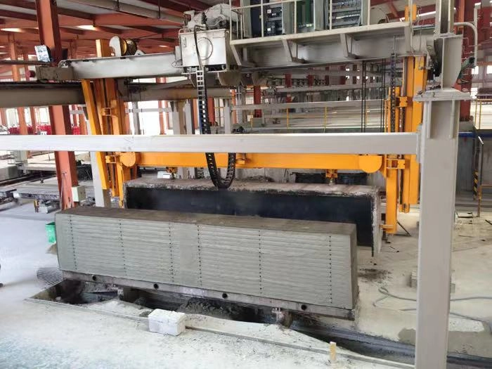
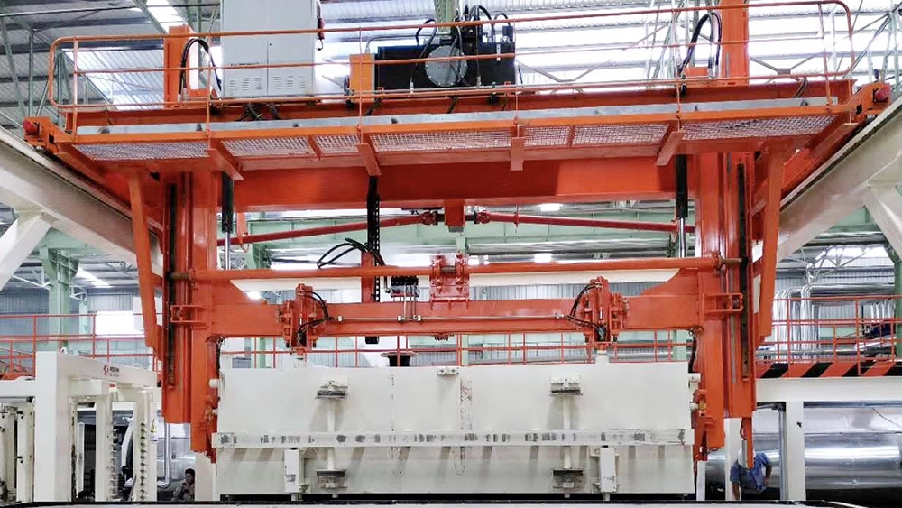
After exiting the static curing chamber, the mould frame travels to the position under the turnover & demoulding crane, which lifts it to the cutting trolley for turnover and demoulding. The travelling rails inside the cutting pit are 60kg heavy rails (65Mn), with one side machined flat rail and the other side machined trapezoidal rail, equipped with H-beams and cutting trolley protective covers. The whole protective cover of the cutting pit adopts an assembled structure for convenient later maintenance and disassembly.

The green body is placed on the cutting trolley. Diagonal positioning pins are used for positioning. When matched with the positioning holes on the autoclave trolley, they prevent the green body from shifting or sidesway caused by uneven cutting force during cutting.
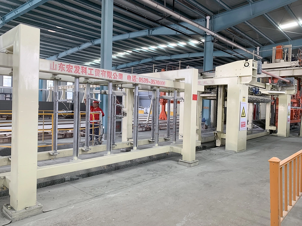
The cutting trolley carrying the green body passes through the side cutter and longitudinal cutter to complete side and thickness cutting. All waste generated from side cutting falls directly into the 70m³ waste slurry tank right beneath the side cutter, which is designed to be 7m × 3m. Three submerged delivery pumps are configured for flushing the cutting pit, washing waste on the turnover table, and conveying slurry to the waste slurry tank. Each slurry pump is individually selected according to pipeline layout, number of elbows, flow rate and head to extend service life. This realizes waste recycling and eases centralized waste cleaning.

A waste mould treatment tank is arranged between the cutting pit and mould frame travelling track. In case of mould collapse, the whole mould waste does not need to be dumped into the cutting pit, avoiding interference to cutting trolley operation and rail cleanliness, and ensuring cutting precision.
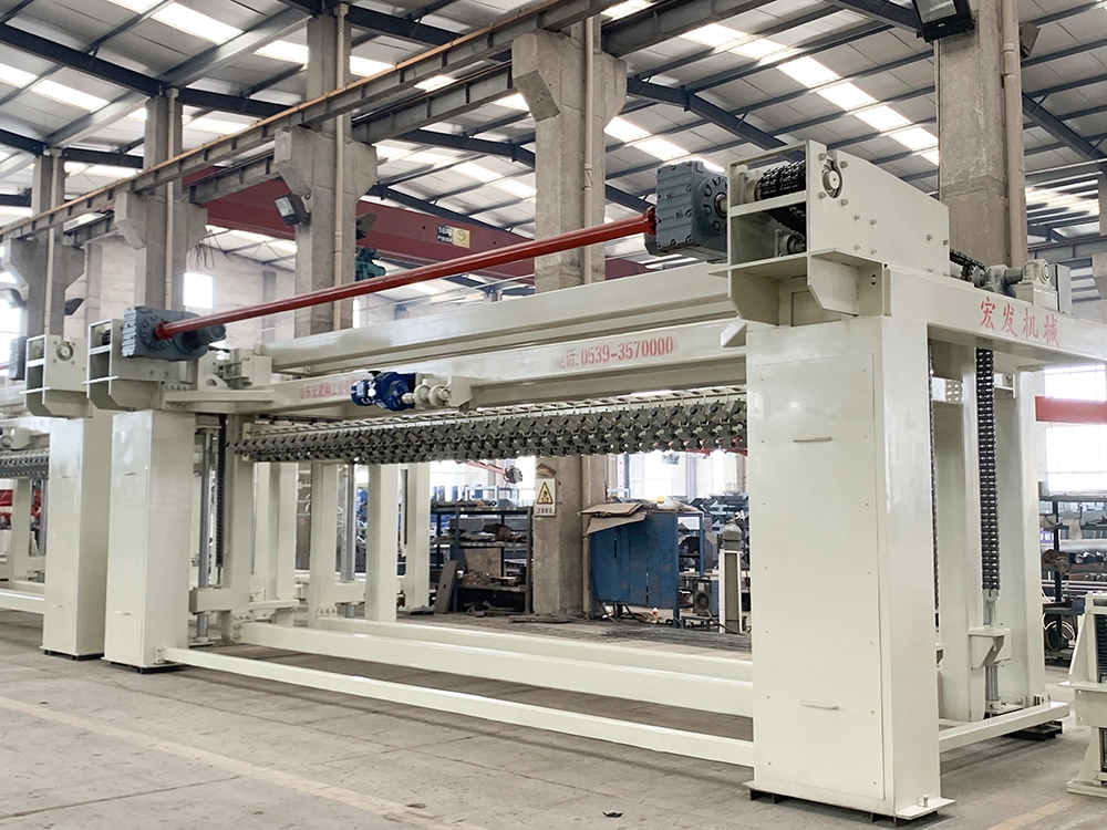
After horizontal cutting, the green body moves forward to the anti-crack groove cutter for grooving, then proceeds to the transverse cutter to finish cutting of block width or panel length. The transverse cutter features a fixed cutting frame; cutting is realized by lifting the green body to form relative movement, ensuring long-term cutting precision. The green body lifting system adopts four-axis synchronization plus rack-and-pinion synchronization, together with counterweights to guarantee stable lifting during cutting.

After cutting, the second cutting trolley transports semi-finished products under the semi-finished handling crane, where the bottom skin is removed by the turnover bottom-removal platform. Matching this high-capacity production line, the turnover table adopts a double-position turnover design with chain conveying, solving low efficiency and cumbersome crane movement of conventional turnover tables. The overall cycle of the turnover table and semi-finished handling crane reaches 3.3 minutes per mould.
All waste generated during cutting and bottom removal is fully recovered and made into waste slurry for reuse. After bottom skin removal, semi-finished products are lifted onto autoclave trolleys by the semi-finished handling crane, with three boards per trolley, ready for the subsequent grouping section.

The turnover & demoulding crane and semi-finished handling crane all adopt rack-and-pinion drive for stable operation and high positioning accuracy. The travelling rails and racks for cranes are pre-machined and assembled on site.
After exiting the static curing chamber, the mould frame travels to the position under the turnover & demoulding crane, which lifts it to the cutting trolley for turnover and demoulding. The travelling rails inside the cutting pit are 60kg heavy rails (65Mn), with one side machined flat rail and the other side machined trapezoidal rail, equipped with H-beams and cutting trolley protective covers. The whole protective cover of the cutting pit adopts an assembled structure for convenient later maintenance and disassembly.
The green body is placed on the cutting trolley. Diagonal positioning pins are used for positioning. When matched with the positioning holes on the autoclave trolley, they prevent the green body from shifting or sidesway caused by uneven cutting force during cutting.
The cutting trolley carrying the green body passes through the side cutter and longitudinal cutter to complete side and thickness cutting. All waste generated from side cutting falls directly into the 70m³ waste slurry tank right beneath the side cutter, which is designed to be 7m × 3m. Three submerged delivery pumps are configured for flushing the cutting pit, washing waste on the turnover table, and conveying slurry to the waste slurry tank. Each slurry pump is individually selected according to pipeline layout, number of elbows, flow rate and head to extend service life. This realizes waste recycling and eases centralized waste cleaning.
A waste mould treatment tank is arranged between the cutting pit and mould frame travelling track. In case of mould collapse, the whole mould waste does not need to be dumped into the cutting pit, avoiding interference to cutting trolley operation and rail cleanliness, and ensuring cutting precision.
After horizontal cutting, the green body moves forward to the anti-crack groove cutter for grooving, then proceeds to the transverse cutter to finish cutting of block width or panel length. The transverse cutter features a fixed cutting frame; cutting is realized by lifting the green body to form relative movement, ensuring long-term cutting precision. The green body lifting system adopts four-axis synchronization plus rack-and-pinion synchronization, together with counterweights to guarantee stable lifting during cutting.
After cutting, the second cutting trolley transports semi-finished products under the semi-finished handling crane, where the bottom skin is removed by the turnover bottom-removal platform. Matching this high-capacity production line, the turnover table adopts a double-position turnover design with chain conveying, solving low efficiency and cumbersome crane movement of conventional turnover tables. The overall cycle of the turnover table and semi-finished handling crane reaches 3.3 minutes per mould.
All waste generated during cutting and bottom removal is fully recovered and made into waste slurry for reuse. After bottom skin removal, semi-finished products are lifted onto autoclave trolleys by the semi-finished handling crane, with three boards per trolley, ready for the subsequent grouping section.
The turnover & demoulding crane and semi-finished handling crane all adopt rack-and-pinion drive for stable operation and high positioning accuracy. The travelling rails and racks for cranes are pre-machined and assembled on site.
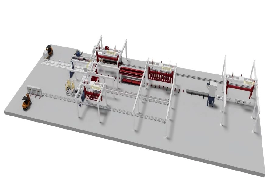 Finished Product Discharging & Packaging Section after Autoclave
After curing, green blocks are delivered to the autoclave discharge line via ferry cart, then transported to depalletizi...

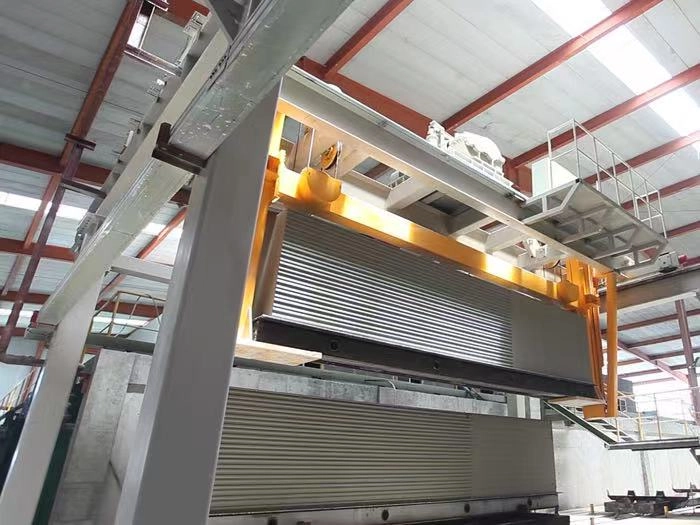 Autoclave Curing Section
This section describes the fully automatic autoclave curing process for semi-finished products. After feeding and steam ...
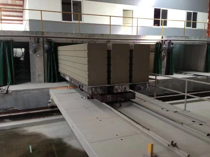 Grouping & Autoclave Curing Section
This section covers the automated grouping and autoclave curing process. Friction-wheel-driven autoclave trolleys with p...
Shandong Hongfa Scientific Industrial&Trading Co.,Ltd ©️2026Copyright © LU ICP B 16041216-4